5. Installation and Setup
🎥 Install Video: A step-by-step installation video is available on YouTube:
5.1 Safety and Personal Protective Equipment
The following personal protective equipment (PPE) is required for installation and operation of the VENTMEDiC® system:
- Safety glasses or goggles
- Hard hat
- High-visibility vest
- Steel-toed boots
- Flame-resistant clothing, as required by site policy
- Protective gloves when handling electrical connections or pressurized fittings
Technicians must also follow any additional PPE or safety requirements mandated by their employer, site operator, or applicable regulatory authority.
5.2 Site Preparation
Before deploying the unit, confirm the installation site meets the following requirements:
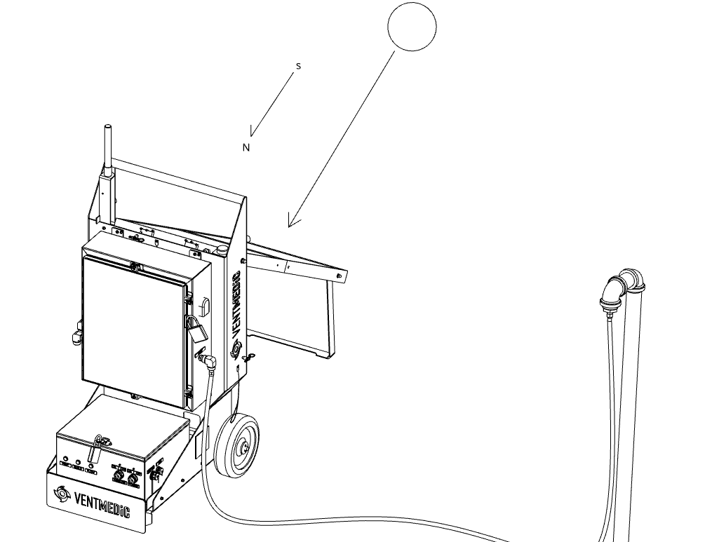
- Confirm the site provides clear sky exposure for the solar panel. Orient as close to 45° south-facing as possible, free from shadows or obstructions at any time during the day.
- Avoid low-lying areas where standing water, excessive mud, or ice could accumulate.
5.3 Unpacking and Inspection
5.3.1 Unpacking
- Carefully remove all outer packaging — do not use sharp tools near the enclosure surface or solar panel.
- Inspect the enclosure exterior for shipping damage (dents, cracks, damaged lid seals).
- Report any visible damage to the carrier immediately using a concealed damage report.
- Remove all packing inserts. Retain packaging for potential return shipping.
- Confirm all Amphenol dust caps are in place on all DTU connectors.
5.3.2 Pre-Installation Checks
- DTU and MIP enclosure doors are fully closed and locked with padlock.
- All Amphenol protective caps are securely in place on unused ports.
- All cables are neatly secured and undamaged.
- Power switch is confirmed in the OFF position.
- Antenna is securely stored for transport.
- Solar panel surface is clean and free from protective films, dust, or debris.
5.4 Unit Placement
Correct placement of the cart is essential for safe operation, reliable communications, and accurate measurement.
- Separation distance: Position the VENTMEDiC® cart at least 10 feet (3 meters) from the wellhead or other gas source, in line with Class I, Division 2 equipment separation practices. Flexible tubing will bridge this gap during gas connection in a later step.
- Place the cart on a firm, level surface to prevent tipping and to maintain correct sensor orientation.
- Ensure there is adequate clearance around the enclosure for door opening, cable routing, and safe operator access.
- Orient the solar panel for an unobstructed sky view — not shaded by structures, vehicles, or vegetation during operating hours.
- Confirm that all enclosure doors are fully closed, latched, and locked before electrical connections are made.
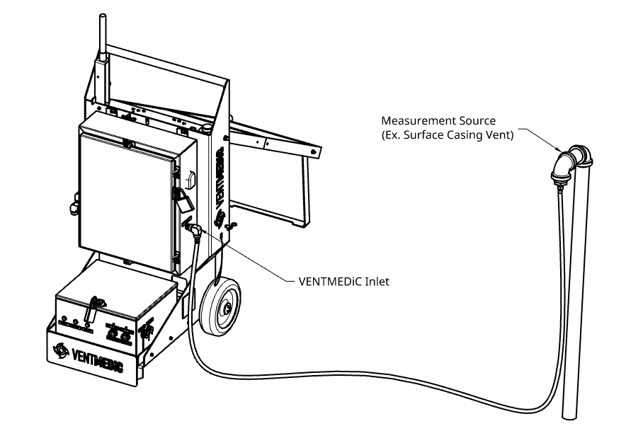

Cart components (for reference throughout this manual):
| Component | Description |
| Measurement Instrument Panel (MIP) | Upper enclosure housing the core measurement electronics |
| Solar Panel | Deployable panel mounted to the side of the cart, charges the battery |
| Data Transmission Unit (DTU) | Lower enclosure with the front control panel, ports, and connectivity hardware |
5.5 Electrical Connections
The DTU provides dedicated ports for power, data transfer, and external connectivity. All ports are fitted with Amphenol protective caps that must remain in place when not in use. Complete all electrical connections before proceeding to power-up.


DTU Electrical Connection Panel ports: Charge, External Power, USB-C, Ethernet, Antenna, Solar Input.
5.5.1 Solar Panel
- Extend the solar panel to its fully deployed position and lock in place.
- Adjust tilt to approximately 45° and orient facing south.
- Verify the solar panel cable is connected to the DTU solar input port.
5.5.2 Antenna
- Extend the antenna mast to its fully upright position and lock in place.
- Verify the antenna cable is securely connected to the DTU antenna port.
- Confirm the antenna has clear sky exposure and is free from obstructions.
5.5.3 Battery Charging
- With the DTU power switch in the OFF position, connect the supplied battery charger to the Charge port.
- Confirm the charger status indicator shows active charging (solid red light).
- Allow 5–10 hours for a full charge. The indicator changes to green when charging is complete.
- Disconnect the charger once charging is complete before proceeding to power-up.
5.5.4 External Battery Port (Optional)
- Purpose: Connect an optional external battery (sold separately) when extended runtime is required in low-solar conditions.
- Ensure polarity and connector type match the specified external battery requirements.
5.5.5 USB-C and Ethernet Ports
- USB-C Port: Used for manual data download from the DTU to a laptop or PC, and for uploading firmware updates. Not required for standard deployment.
- Ethernet Port: Used to connect the DTU to an external internet source (e.g., Starlink router) when enhanced connectivity is required beyond cellular. Not required unless cellular coverage is insufficient.
Previous: 4. Key Applications · Next: 6. Operation